new
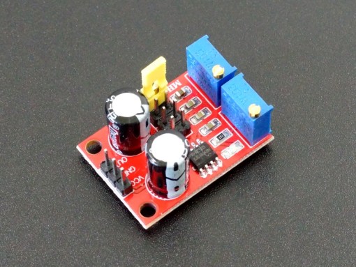
NE555 Timer Module
DESCRIPTION
The NE555 Timer Module incorporates the NE555 timer IC on a small board with the ability to adjust the frequency and duty cycle of the output.
PACKAGE INCLUDES:
NE555 Timer Module
KEY FEATURES OF NE555 TIMER MODULE:
Operates NE555 in astable mode of operation
Up to 500 kHz operation
Frequency range jumper and adjustment pot for finer control
Duty cycle adjustment pot
4.5 to 16V operation
The NE555 timer is one of the oldest chips around, but it is still useful for creating rectangular waveforms such as for lower speed clocking of circuits or for creating a timing pulse. If you check out the datasheet for the chip itself, it shows just how versatile the part is.
The bare NE555 chip which we also sell is fairly easy to use and only requires a couple of resistors and capacitors. The chip uses the RC time constants of the selected resistors and capacitors to set the output frequency and duty cycle. Once the novelty of wiring one of these up from scratch wears off, this little module includes all the parts required to implement the basic timing circuit (a-stable mode of operation) so that it can be easily included in a project or to use as a low cost frequency generator.
Setting Frequency
There is an 8-pin header that provides a jumper setting to select different frequency ranges.
The jumper puts different value capacitors in the circuit to change the time constant. The low end goes down to about 1Hz. The high end goes up to about 500kHz before the chip becomes unstable. The NE555 chip itself is actually guaranteed to 100kHz. As you push the frequency above that, the output becomes a little less rectangular until the chip eventually becomes unstable.
The multi-turn potentiometer near the frequency range jumper provides for fine control over the frequency once the basic range is set. Turning the pot CW increases the frequency, while turning it CCW decreases it.
The board includes an LED which is lit when the output is low and off when it is high. When the frequency is higher than about 30Hz, the LED will appear to always be lit since the blinking will be too fast to see.
The table below shows the range we measured on a sample basis. This will vary a bit between modules depending on the tolerances of the components used.
Frequency Select Jumper Ranges
